Module Overview
The aim for this module is a board with 4 different oscillators, each of which can be triggered by a pulsed clock signal, or a pushbutton input.
Each oscillator will be based on the 555 timer for simplicity. I want the pulse input to be capable of triggering outputs of different lengths, which should let me generate short tones which can be filtered into chirps and pops suitable for electronic high hats sounds, or longer tones which could be the basis of some booming bass drum sounds, or an 8 bit cymbal crash. Medium length tones should be capable of producing snares and tom sounds if the right kind of filtering is applied. Each oscillator will have independent pitch control and I will use an adjustable duty cycle which gives a wider range of sounds than a fixed duty cycle.
I am leaving all the outputs separate for now, as I will want to process them all differently to get the desired sounds, before being mixed together later.
Developing the Circuit
After a bit of playing around, this was the final circuit I settled on.
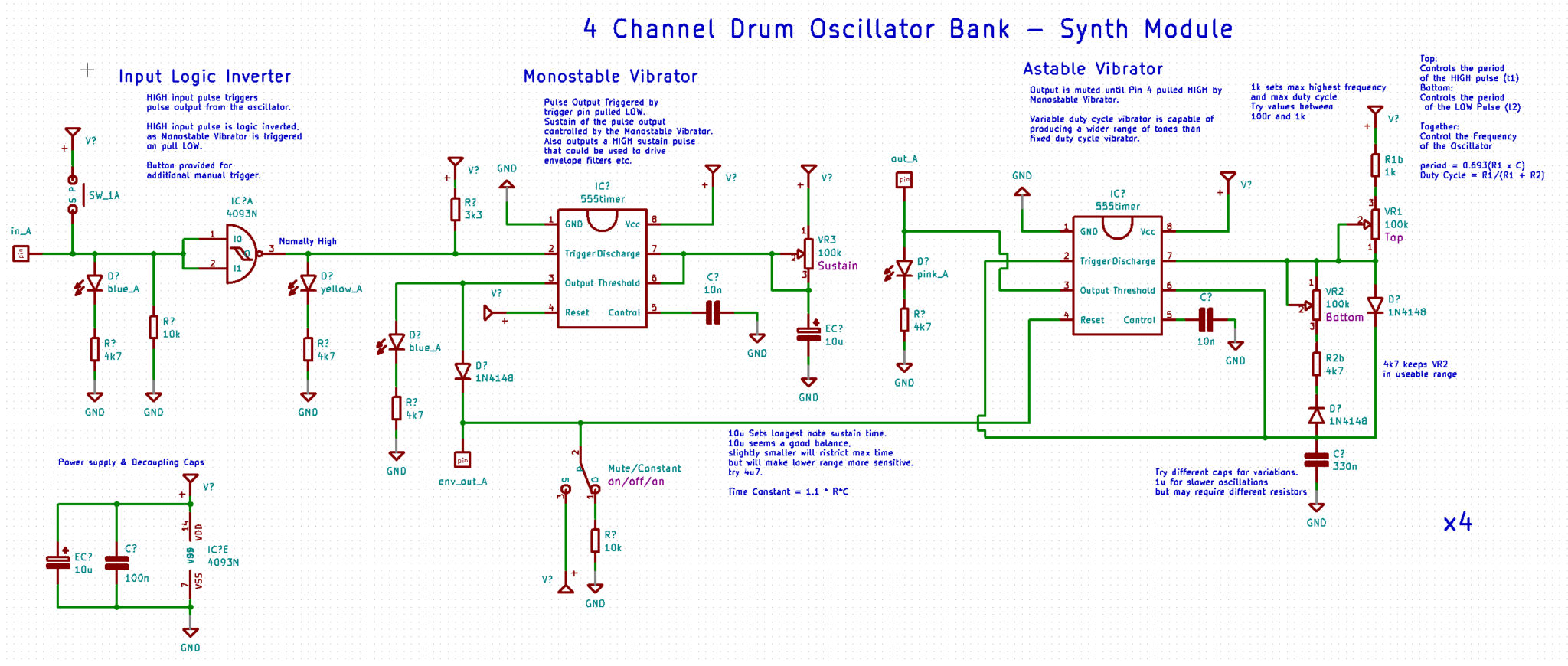
Astable Vibrator
Working backwards, from my desired output through to how I would control this, we have a 555 arranged as an Astable vibrator. The diodes included in the RC control section, allow different resistances to control the Time High (T1) and Time Low (T2) of the 555s output. This gives us a far wider range of tones than is available from a fixed duty cycle oscillator, but it does mean that the pitch of the oscillator is controlled via the interaction between these two potentiometers, so the output pitch is less predictable than a fixed duty cycle oscillator. The resistors I picked, along with the 330n capacitor kept the entire range of the pots within the audiable range, however it does ristrict some lower frequencies, so I might want to try with a slightly larger capacitor, with the risk that I will have to adjust the resistance to keep the pot sweep in the audiable range.
Monostable Vibrator
The reset pin for the Astable oscillator, is held LOW by the Monostable Vibrator. This disables the output completely. When the monostable trigger pin is pulled LOW, it triggers a HIGH output pulse, the period of this pulse is set via the RC circuit in pin 6 & 7. the 10u cap gives a maximum pulse time of about 1 second, which is far longer than any drum hit is likely to be, but some of these sounds might make nice bass drops as well. Once I have the whole system working, I might find I want to be able to more accurately control shorter pulses, in this case I will just reduce the size of this cap.
EDIT: Due to the layout I picked and the addition of the switch to mute or set the circuit to constantly output, I also added the diode between the Monostable & Astable oscillators, to stop Vcc being fed back into the first IC. The mute switch also doesn’t mute so that needs work. This probably would have been better on the input to the monostable vibrator, It just ended up the way it did due to the layout and some spare space I had down the bottom. Once I move to PCB I will move it to the more logical place in the circuit.
Logic Inverter
Not much to say about this, except I wanted to make sure that this drum sound would be triggered by a high pulse, but the monostable vibrator required its trigger pin to be held at Vcc then pulled low to trigger the pulse. I added a switch so I can manually trigger drum hits, I may even find it is quite playable without a clock – we shall see about that. As the logic IC has 4 gates available, it makes a lot of sense to have 4 of these circuits all on a single board. This should give me Bass Drum, Snare Drum, A Tom & High-Hat sounds available after some additional filtering. Everything I need to build sick trap beats.
Layout
I broke some of my usual rules for stripboard layouts. I tend to avoid using flexible cables to join parts on the board, but I wanted to prioritise the control layout, and make a long and thin strip with outputs at the end for easy wiring. I also made sure any cables that ended up coming out at the bottom of the circuit board would also be available at the top. this means I can wire it up with everything connected at the top, leaving my desk free of spurious wires.

I decided to make each channel on an independent board, this will make it easier to switch out individual oscillators later. The first version of this synth will have 4 of these modules.
I separated out the input controller, as this greatly simplified the layouts. This board will be used as the trigger for 4 of the above modules. Each stage of the circuit has an LED so its easy to follow what the circuit is doing.

Drum Sequencer
For a basic drum sequencer, I want to use an Arduino Nano. Its going to have 4 pulsed outputs, but I need a way to vary the output timings so I can have different, and changeable drum patterns.
Eventually I will make sure this can sync with our filter sequencer, as that has 8 “beats” with a clock of 16 pulses, I want the drum patterns to have 16 individual beats, which can be split between any of the 4 drum channels and I would like to be able to humanise or add some swing into the timings of these beats.
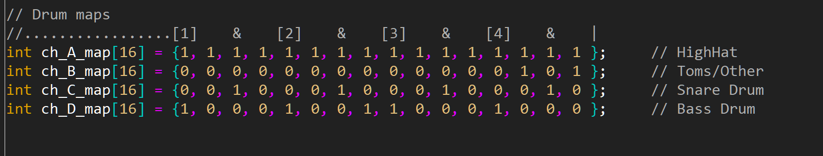
For testing I just need a few simple patterns, and the ability to change tempo. To make the drums easy to program, I will use 16 byte arrays, one for each drum channel. This will have a sequence of 0s and 1s to represent hits or mutes on each drum channel.