Project Introduction
So, this is a project I have been mulling over for a while, I have finally found some time to start working on it.
I have been playing around with guitar FX for many years now, I was always interested in finding the most esoteric or unusual sounds I could, and trying to make something musical with these ridiculus sounds.
Two of my favourites ever are the Maestro, Filter Sample & Hold, an envelope controlled filter with the option to control the filter cutoff via a random voltage sampler, which step modulates the filter cutoff for a bouncing synthy effect. And the Earthquaker Devices Bit Commander, which can produce some amazingly thick Bass Heavy and glitchy 8 bit sounds. Both of these effects deviate significantly from the typical guitar sound, but I have always felt we can go further.
There seems to be a big divide between the guitar stompbox FX world, and the DIY modular synth world, and I have never been able to tell why, the modular synth world certainly has a tonne of interesting sounds and effects that guitarists might find use for, so this project has grown into building a modular synth from the ground out, but paying special attention to making this work for people playing guitar. I want to mix analog and digital control, and maybe eventually add some DSP modules. The whole synth needs to be able to be beat synchronised, and I want to develop my own clock with a tap-tempo to do this.
I am going to attempt to make each module very specific, to try and show how small sections of circuits can be used on their own in different ways. How modular can we make a modular system?
Test Oscillator
First stage of the synth test build was an oscillator. Although I had some previously built, they were already contained in other projects and I didn’t want to take them apart for testing this. I also happened to have a couple of PCBs in a drawer from a colleague for the “Pink 555 Synth”. A dual 555 timer based oscillator circuit, so I thought, what the hell, let’s build it and see how it sounds.
Initial impressions were less than overwhelming. The pots operate in reverse, and many of the selectable caps using the 8 dipswitches, produce frequencies too low to really be useful, however there were some interesting sounds available, and it sounded quite different to the other oscillator I was interested in using, so for now I will stick with it while I test.
As it turns out once I started running this through the filters documented later, I had a serendipitous discovery of some really nice drum & rhythm sounds that can be made with this circuit, and I hope to be able to make a modified version, triggered via pulses from a microcontroller, that could be used for a drum machine that will now form part of the synth.
Maestro – Filter/Sample&Hold Circuit
The next part to start testing was the filter section. I isolated the filter circuit from the M:F/S&H, losing the envelope detector and the voltage sampler sections, leaving behind just the 2 stage bandpass filter, with 2 potential points to inject a control voltage.

I ended up injecting a control voltage at the point CV2. Voltages from 0v to +9v controlled the cutoff very nicely, and I was able to get some very musical sounds using both the test oscillator circuit, and a guitar input. The sound is very similar in scope to a wah pedal, but far more extreme. I would love to put one of these in an old wah chassis for that extreme Joe Satriani wah sound.
I do want to do something with this for the current project, as I love the sample & hold function from the Maestro pedal, the problem I had using it in any kind of musical setting, was syncing up the free running LFO to any kind of useable beat, once in a band or song context, when drums are leading the tempo. Controlling this cutoff digitally will let me beat sync the effect perfectly, and should lead to an entire universe of fun and useable sounds.
Funky Filter Circuit
Despite loving the sound of the circuit above, I also wanted something that would be easily configurable as Low Pass, High Pass and Band Pass. I found this circuit after following some links on Look Mum No Computers webpage, and I set about building.
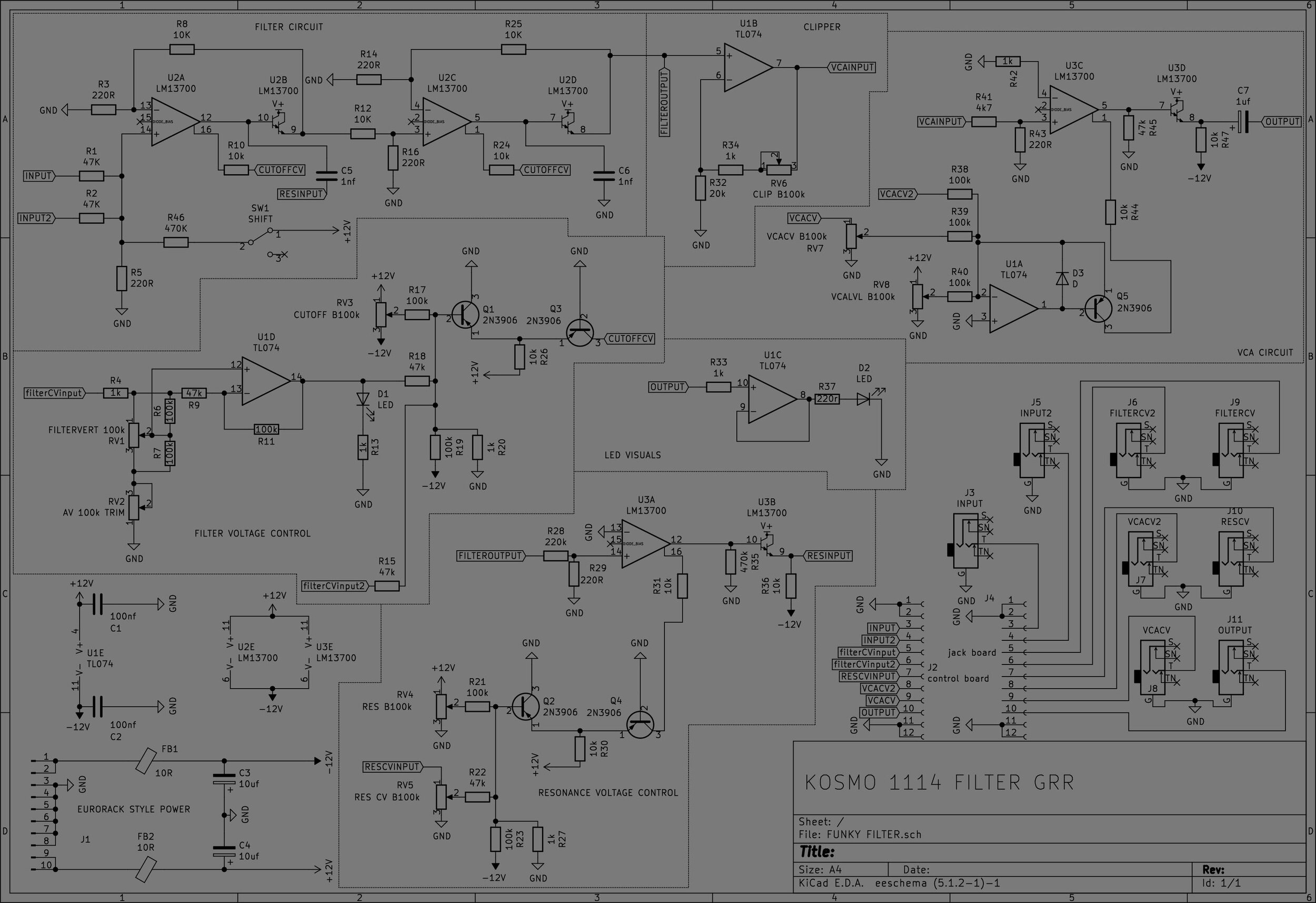

This circuit sounded AMAZING. Instant modular vibes and resonance induced overtones that seemed to be missing from the M:F/S&H circuit. This definitely wins the competition for further development. I hope to use the F/S&H filter as well, but for now it will take a backseat and my focus will be on this circuit.
NOTE: Layout has a cut in the wrong place. 5th line down on the first board, omit the cut shown on this line.
NOTE: Blend Pot Pin 2 to GND
Microcontroller to Control Voltage Testing
I started working on a circuit to convert the 3.3v or 5v output from a microcontroller, into the 0v to -9v control voltage required to control the filter circuit we tested above.
Running some calculations, this is the circuit I came up with. Its incredibly simple, but I am yet to test it out to see if it will work for our purposes. I am going to aim to keep circuit snippets like this as simple as possible, and only add complexity if required.
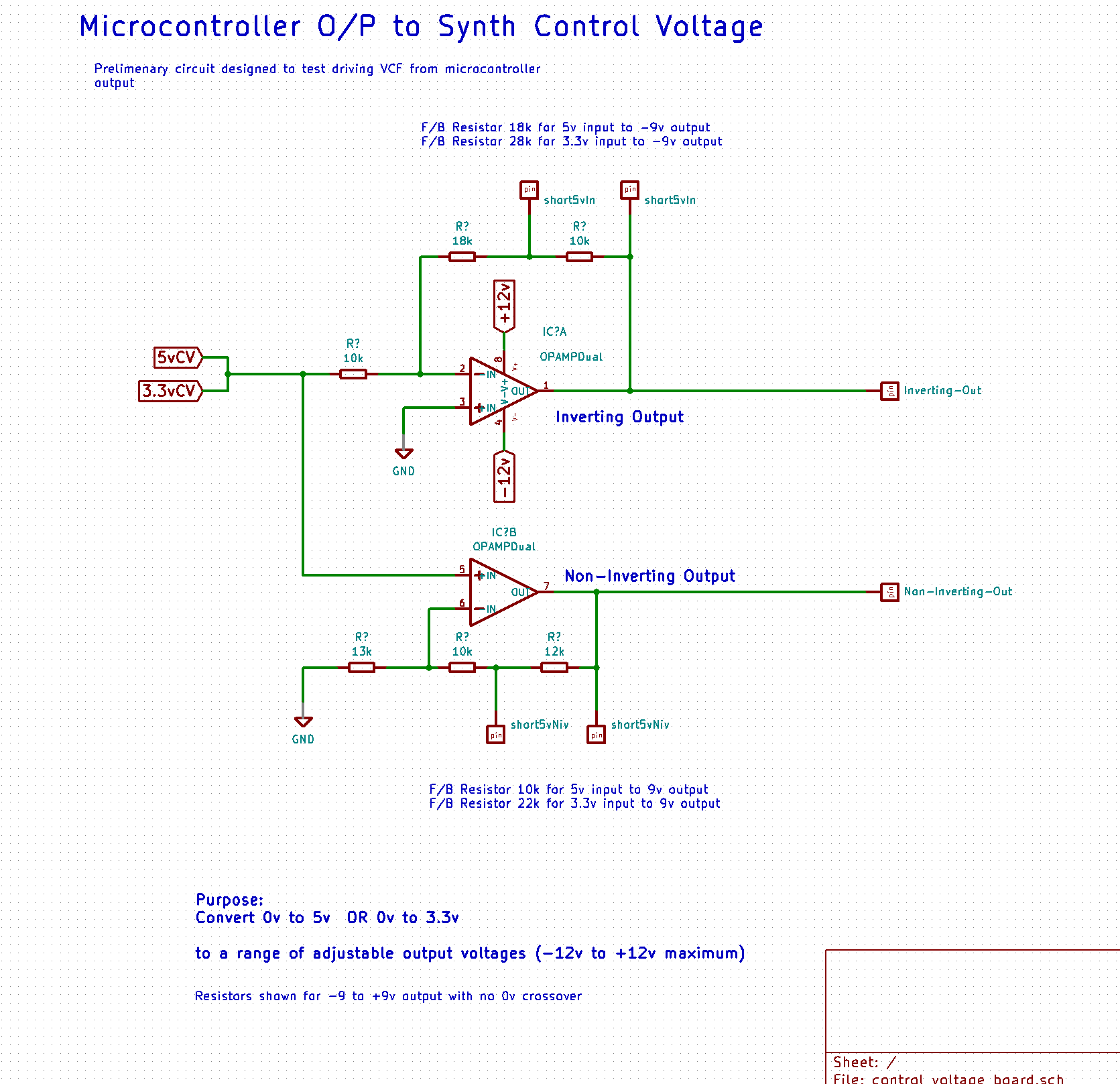

This circuit worked to change the voltage level, however it was not ideal for our purposes. The problem with this circuit, was the supply voltage. At the moment it was powered from my pedalboard power supply, which gave me a Vcc of +9v and Vee of -9v. This means that unless we select a rail-to-rail capable op-amp, our output will not be able to atchive the swing required for our control voltage.
This might not matter, as we can adjust the sensitivity of the CV input circuit, and the majority of the “vocal sweep” range of the filter, where the resonance band sits nicely in the mids frequency range happens in the first half range of the control voltage, however, the aim is to make a circuit that can be easily configurable to do everything we need, so we can use it for the same purpose in different places. It Must Be Modular!
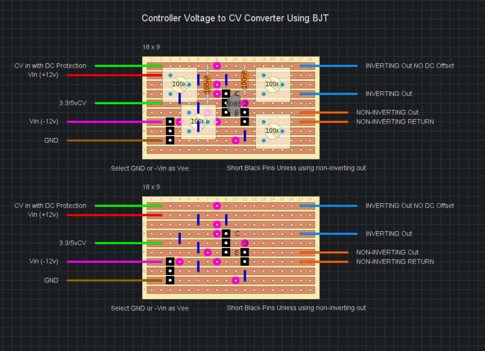
Microcontroller to Control Voltage Testing 2
I also wanted to see if we could use a BJT amplifier to scale our control voltage. This was the layout I made, I wanted to be able to play around with the gain and bias points of the transistor to achieve a clean waveform output, so every resistor is variable. This circuit may also be useful as a generic audio amplifier later.
I wasn’t sure if we could get this working adequately with the bipolar power supply, so I added an option to easily reference Vee to GND or to -Vin.
The Step-Sequencer
To control the filter cutoff, we require a control voltage. I want to be able to replicate the stepped sound of the mastro filter, but in a controllable manner. Therefore we can use a simple digital sequencer with an analog voltage output.
I used an ESP32 for this, as it is a platform I am very familiar with. I wrote the outline of the code in a couple of evenings, it is very far from complete, but it is sufficient to start testing by driving the filter cutoff. Find the code @ https://github.com/PanGalacticTech/ESP32_sequencer.git
As well as the analog voltage output, I have added a 50% Duty cycle clock, and an adjustable duty cycle clock pulse, in time with the step-sequencer. These can be used as a master clock to sync up with other effects or sequencers.
Eventually I will add a second DAC output, and each DAC will be able to be switched between the sequencer and an LFO output.
I used the Op-Amp based voltage converter, combined the 2 circuits and this was the result I got from it:
It’s certainly a start, I would like to get a greater range of voltages from the conversion circuit, I think the voltage swing is not high enough, as it is unable to reach the rails, and this is limiting the total sweep of the filter. A Rail-to-Rail Op-Amp might help, but it may just require a higher supply voltage for the control voltage driver circuit.
Coming Next
The next part of the synth I want to work on, is a drum sequencer module. This is going to take the pulse from the master clock of the sequencer, and subdivide it to produce a half beat, beat, and bar pulse output. I can then use logic gates to produce different drum patterns.
This could be done with another microcontroller, but it seemed like an interesting project to try and make a module based entirely off a clock pulse and logic gates.
Follow the progress of this module in Part 2.