The first problem to solve for the Electrolysis Machine project, is making sure we can accurately measure the supply voltage and current that will be pushed through the probes, and the hair follicle.
The target current to deliver is between 0 and 2mA, and to keep things ultra simple for this test, we can use a simple current limiting resistor to limit the maximum current, and max voltage seen at the ADC (analog digital converter) pin of the 5v Arduino Nano development board. We can then use a variable resistor or rheostat to control the current between 0-2mA.
To measure the current, we will measure the voltage drop across a shunt resistor. Typically it is best to keep the resistance of the shunt as low as possible, so that it does not affect the current through the circuit, but this will reduce the range of voltages detected by the ADC. In order to increase the sensitivity of the ADC, we can use a larger resistor. We are not worried about changing the current in the rest of the circuit, as our purpose is not an ammeter, it’s controlling a very small current in series with the shunt resistor.
Simulating the Circuit
As this is a very simple circuit, and we are not concerned with transients, we do not need pspice or similar at this stage. I made an excel spreadsheet that would let me try different values for each resistor, this will calculate the current flow though the circuit, the voltage drop over the shunt resistor, and then even what range of values we should be able to detect using the Arduino ADC. I set the voltage source to between 15 and 20 volts, however this may need to be boosted later to push the required current through actual flesh which will have a variable conductance compared to the fixed resistors.
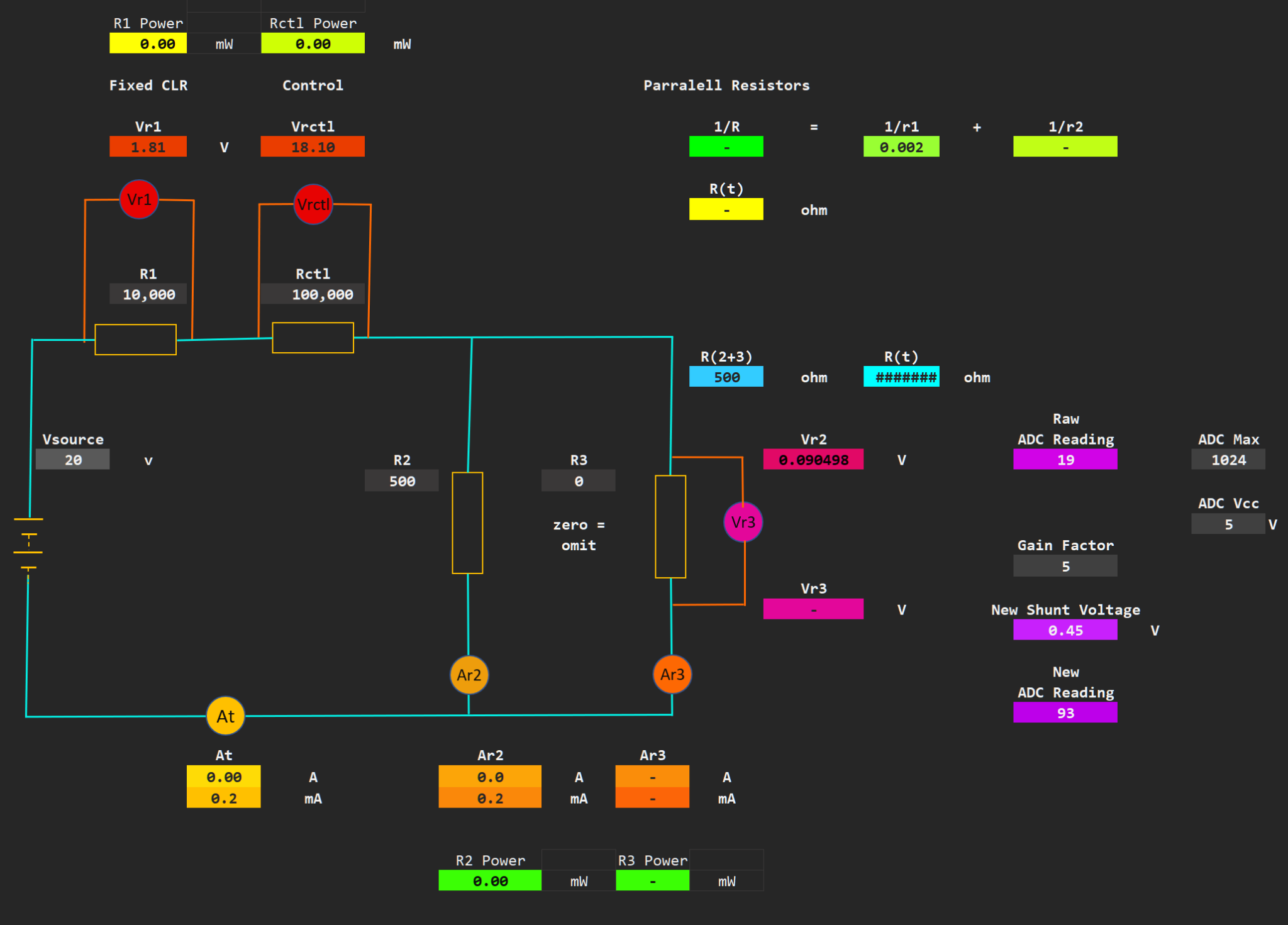
Using this simulation, I selected 10k for the Current Limiting Resistor, 100k to 500k for the variable resistor, and 500 ohms as the shunt resistor. This wouldn’t give me the full range of 0-2mA, but it would give me enough of the range to compare the calculated current value using an Arduino, measuring the potential difference/voltage drop over the shunt resistor.
Using these values I was expecting an ADC reading of ~19 to ~195.
This is not a huge range to work with, and may not give me the resolution I require for the final project, but its a place to start. With these values I would be able to amplify the measured voltage by a gain factor of 5, and not reach the 5v limit of the ADC pin of the microcontroller. So a later implementation will likely use an op-amp with a gain of 5 to increase the sensitivity of this system. I can also reduce the resistance of the shunt resistor, and increase the gain to deal with lower currents.
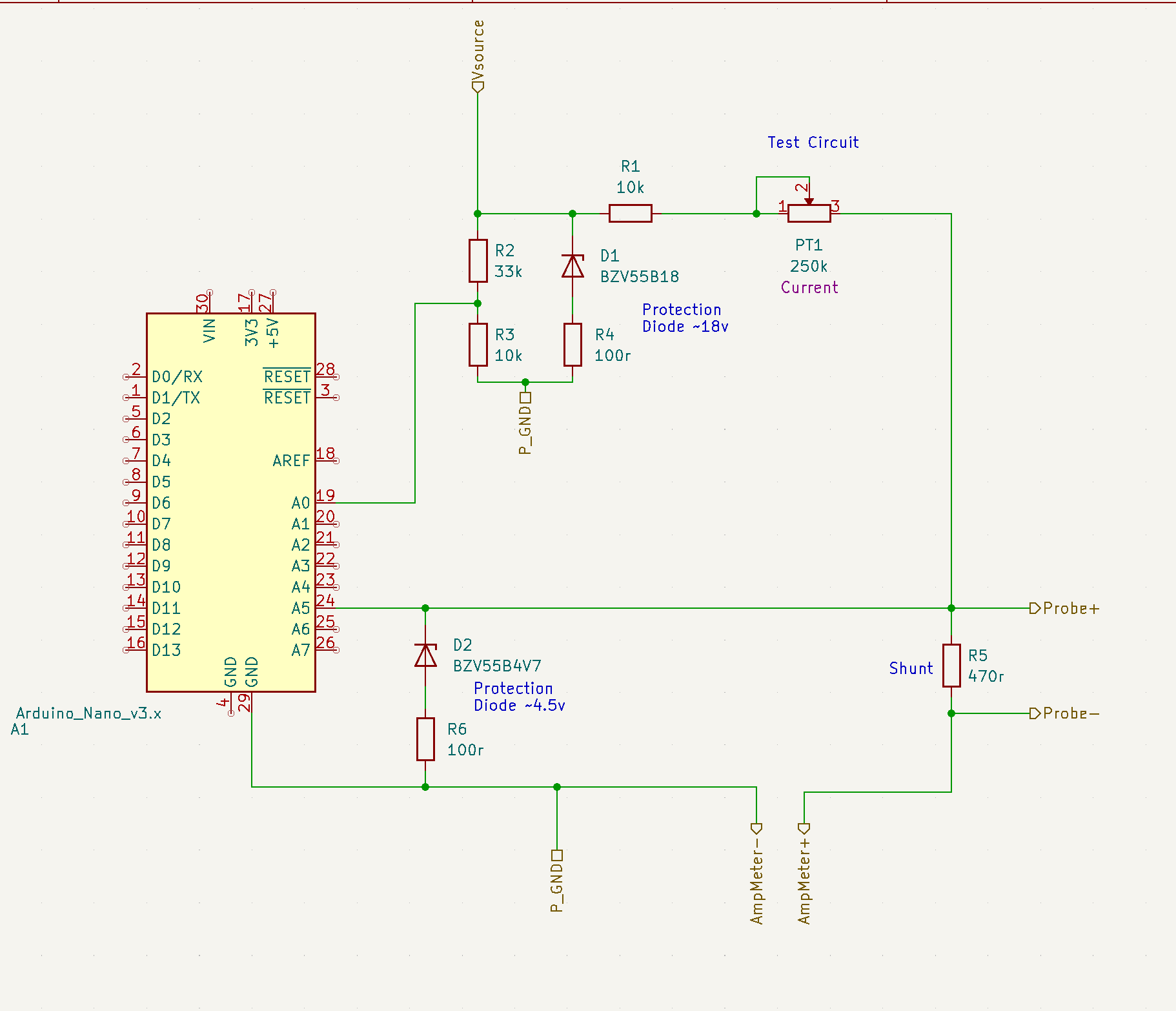
For my actual test circuit, I placed reverse biased zener diodes over the Vin and to the input of the microcontroller ADC, at 15v and 5v respectively. This should clamp the voltage if it creeps over these values, although there should be no way of the voltage drop over the shunt resistor exceeding 5v if the supply voltage does not increase beyond 20v. I used an ~ 3:1 voltage divider on the Vsource line to drop the voltage to below 5v so I could also track the Voltage of the power source, along with the voltage drop over and the current through the shunt resistor.
The Code / Software
Or: Still looking for a clean solution to convert floats to char arrays to use with sprintf() functions.
Setup
First, in the setup we do some quick calculations to set variables we can use later to convert to scale our real voltages. We could do this maths manually and enter in the scales, but this way will let others quickly change some input values and forget about doing the maths if anything changes.
void setupVinConversions() {
  voltsPerADC = ADC_MAX / 1024.0;
  Serial.print("Volts Per ADC: ");
  Serial.println(voltsPerADC, 6);
  vin_ADV_offset = (VIN_ADC_OFFSET_HIGH + VIN_ADC_OFFSET_LOW) / 2;
  Serial.print("Vin ADC Offset: ");
  Serial.println(vin_ADV_offset, 6);
}
Loop Functions
Then the loop simply samples the two ADC input pins, and does the maths on them to calculate first the true Vin value, then the Shunt voltage drop, and from this the current flowing through the shunt resistor.
void calcVin() {
  f_Vin_sampled = u_Vin_ADC * voltsPerADC;
  f_Vin_scaled = (f_Vin_sampled * VIN_SCALER) + vin_ADV_offset;
  Serial.print("  Vin Scaled: ");
  Serial.print(f_Vin_scaled);
  Serial.print(" |");
}


void calcShunt() {
  f_shunt_Vdrop = u_shuntADC * voltsPerADC;            // Measured voltage drop across shunt resistor
  f_shuntI = ((f_shunt_Vdrop / SHUNT_RESISTOR) * 1000) + SHUNT_CURRENT_OFFSET;
  Serial.print(" Shunt Vdrop: ");
  Serial.print(f_shunt_Vdrop);
  Serial.print(" Shunt Current: ");
  Serial.print(f_shuntI);
  Serial.print(" mA ");
}
To tidy this up and get rid of the long strings of Serial.print, I would love to save all these variables into one string using sprintf for printing a formatted string, but I have not found a satisfactory way of turning floats into strings at this point in time.
Results
The results are fairly accurate, I was not able to totally reduce current to 0mA, it minimum was closer to 0.2mA, and I achieved about 1.8mA. The calculation from the Microcontroller was fairly accurate, but the response was not linear, it trended towards under reporting the current at the lower side of the range, and tended to over report the current at the higher end of the range. I should be able to come up with a calculated offset to replace the fixed offset to make the reporting more accurate across the entire range, but for now, a +/- figure of approximately 0.2mA is sufficient for our purposes.
Conclusion
The results were sufficient for this test, the current was able to be measured with some degree of accuracy, however I will want to look into methods to increase this accuracy. Moreover, as the circuit develops into something with a less perminantly fixed current, i.e. replacing fixed resistors with PWM drive, I am sure both the method of measuring the voltage drop across the shunt resistor, and the shunt resistor are going to have to be adapted.
I believe the next step in moving this particular sub-system forward will be the addition of a small amplifier to increase the sensitivity of the ADV, and buffer the signal from effects happening around it.