Generating high voltages from a low voltage DC input using a 555 timer as a basic Switch Mode Power Supply.
Warning!
Do not try this yourself.
I bear no responsibility of the consequences should you choose to build this circuit.It produces potentially deadly voltages, and its perfectly capable of stopping your heart.
THIS IS NOT A TOY.
legal disclaimer
This Switch Mode Power Supply circuit can generally be found online by searching for “Nixie Tube Power Supply”. I initially saw it described as a 400v power supply from an 18v input.
I wanted to build this circuit to play around with battery powering some valves for a high voltage valve preamp, but I figure this circuit is interesting and was worth writing about.
So lets have a look at the circuit:

The circuit itself is simple, an astable 555 timer provides a regular clock pulse to the gate of a MOSFET (Q2). This MOSFET acts as a switch, when the Gate is driven high, the MOSFET conducts, when the Gate is pulled low, the MOSFET stops conducting and acts like an open circuit.
During the first stage of operation, when the gate is driven high, the MOSFET is closed-circuit, and current can flow through the inductor to GND. This creates a magnetic field around the inductor, effectivity storing energy as a magnetic field.
During the 2nd phase of operation, the gate is pulled low and MOSFET is open-circuit, the magnetic field collapses, inducing a current in the inductor. This current is only able to flow in one direction, through the flyback diode and to the output where it is smoothed by a capacitor.
The trick with this circuit is in the switching frequency. If we switch the MOSFET on and off fast enough, we move back into the first stage, charging the coil, before it has fully discharged. This is how it generates such a high voltage output from a low voltage DC input.
The final interesting feature is the feedback loop through a trimpot, to the base of an NPN bipolar transistor. This connects to the control pin of the 555 timer so the circuit should be self regulating, as the voltage at the output drops, the frequency should increase to compensate and vice versa. The output voltage can be controlled using the trimpot in this feedback loop.
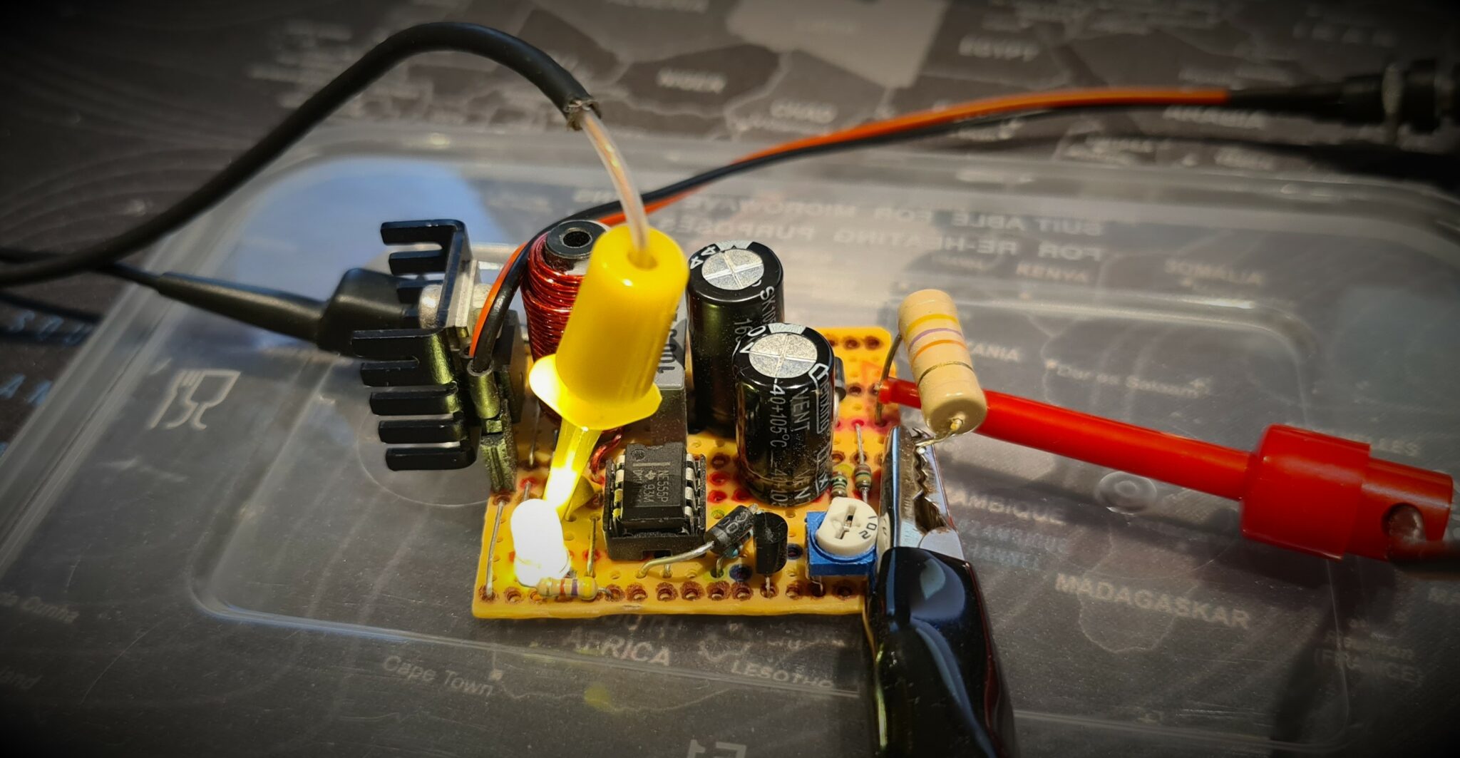
This is the layout I made to test the concept out:

After a first round of testing, I ended up adding a 1N4005 diode in parallel to R2 (10k ohm attached to pin 7 of the 555 timer). This is to allow the 555 timer to produce a duty cycle of less than 50%. I also added a heat sink to the MOSFET as I was expecting this to generate some heat during operation.
Here is my finished circuit, hooked up to all the equipment I would need to test it.
I soldered a 47k ohm resistor from output to ground to act as a load during testing. This value was chosen to ensure the power output was within tolerance for resistors I had in stock. This one came out of a vintage TV repair booklet; I don’t know what the exact power rating it is but it looked chunky enough to handle whatever this circuit could deliver. I took the “advertised” output of 400v and calculated a max current of 8.5 mA through the load resistor. This means the max power output should be no more than 3.4 W. I assume the output voltage will be well under the advertised voltage as I was using 12v DC as my supply voltage instead of 18v, so this seems like a safe assumption for now.
I made sure the board was insulated from the surface, and there was nothing much nearby that could catch fire, then powered the board on with a 12v power supply. This is the result:
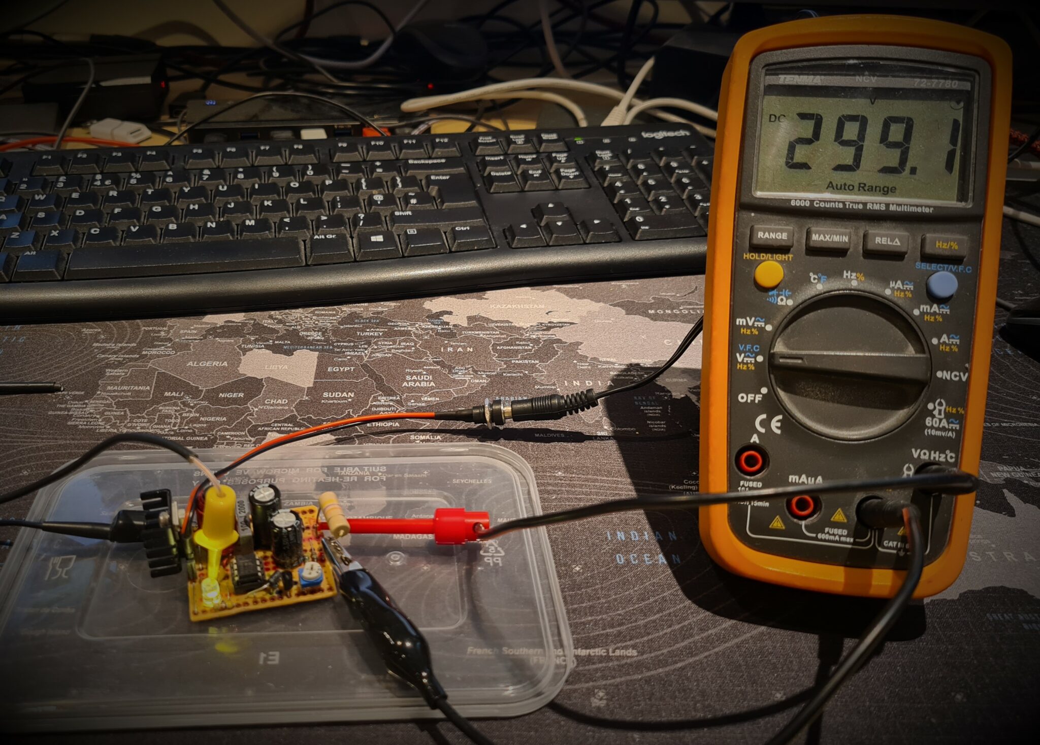
Success! Almost 300v out of a 12v power supply. No magic smoke, yet, although after about 10 minutes, some amount of heat was certainly being generated. The 555 timer and the MOSFET both got quite hot. The voltage stabilised at a maximum of about 290v after a few minutes.
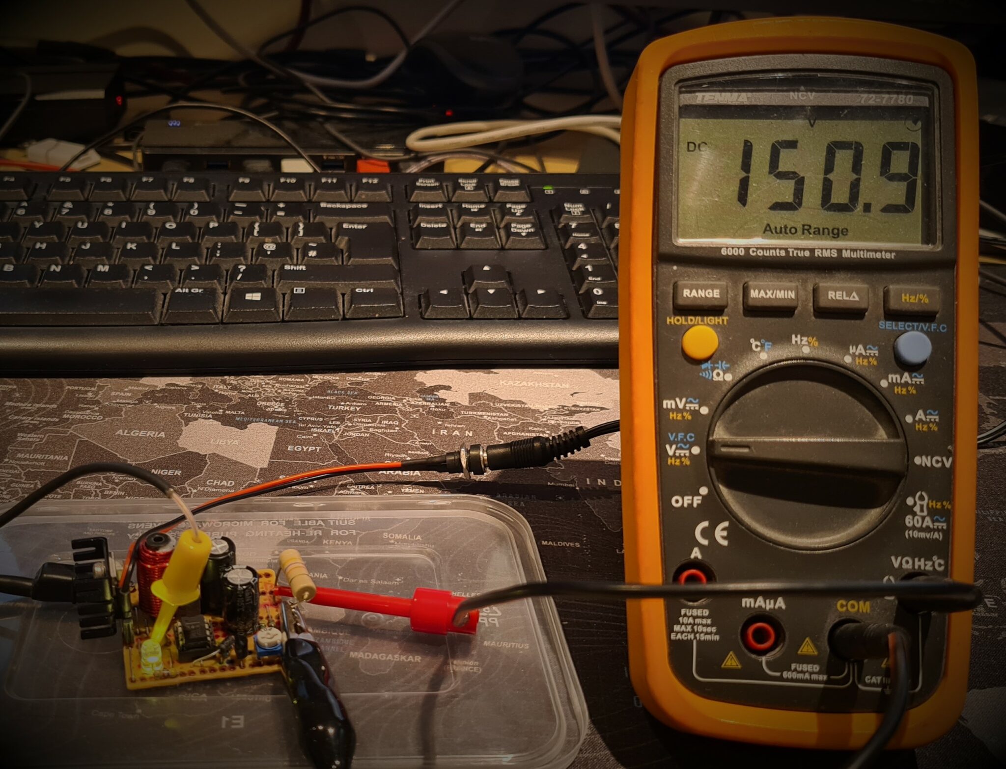
The trimpot changes the frequency of the oscillator, turning it down turned the voltage down from almost 300v to 150v, so there is a wide range of possible output voltages from this circuit.

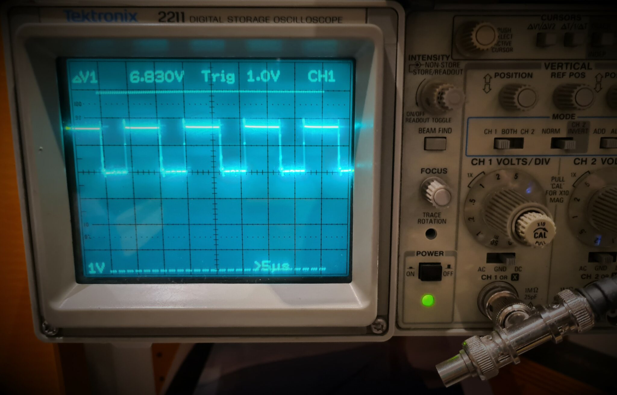
The oscilloscope hooked up to the output of the 555 timer shows us how the changing frequency affects the voltage output.

So for my first foray into high voltage Switch Mode Power supplies is a success. Now what should I do with this?
If you have any ideas for what I should use this for, or any other comments, please leave a message below.
Hi my name is Aldo Rios. Couldn’t you put that power to a breaker and have a small electrical panel and provide ac outlets from that 12v supply or how many.if at all..I have some ideas that I would like to share later on.isbi possible to make a12v inverter then step up that power to step up another power supply to create enough power to supply a small studio apartments with such low power.
This is not an AC supply, it’s a DC output. It would also be exceptionally low power for an outlet. Even if we assume 100% efficiency, power in is 12v at a max of about 2.5A.
12v*2.5A = 30 W
If that voltage is set to 240v, i.e. European standard, then:
30W/240v = 125mA
This circuit is suitable for DC powering of low current audio equipment. Valve Amplifiers are likely to be the best use case for this kind of power supply.
Hi. Can this be used as a high voltage souce for checking the high voltage detection circuits. these detection circuits draw a very low current, therefore no problem with the power requirments. My concern is can this circuit supply a voltage with minimum variation. Thank you
Hi Honey badger, this circuit is typically used to provide power for Nixie tubes, or somtimes preamp tubes used in small footprint tube amps. The voltage output from this circuit is fairly stable, but will sag under load, it is also fairly sensitive to changes to the trimpot, but may be suitable if you replace the trimpot with fixed resistors. As with most electronics projects, I find the best way to see if something will work is to try it!
I’ve used this circuit to power tube preamp guitar effects integrating a regulator for the tube heaters
It works well using a 12v 1a power supply
I’d be interested to know if this circuit has a bleed resistor to discharge the HV cap when the power is disconnected
I’m very interested in understanding what each component actually does
Would adding some filtering to the feedback loop further reduce any noise if it were present
Thank you for this great article it’s really helped me to understand more about this circuit
Most articles I’ve read whilst researching a 555 smps circuit have been well over my limited electronics knowledge but yours definitely makes it much clearer
I’m basically a hobbyist making guitar effects and have ventured into using sub miniature tubes recently on my breadboard
Thanks again