Circuits for Power Supplies, Motor Drivers, Battery Chargers & Other Utility Functions
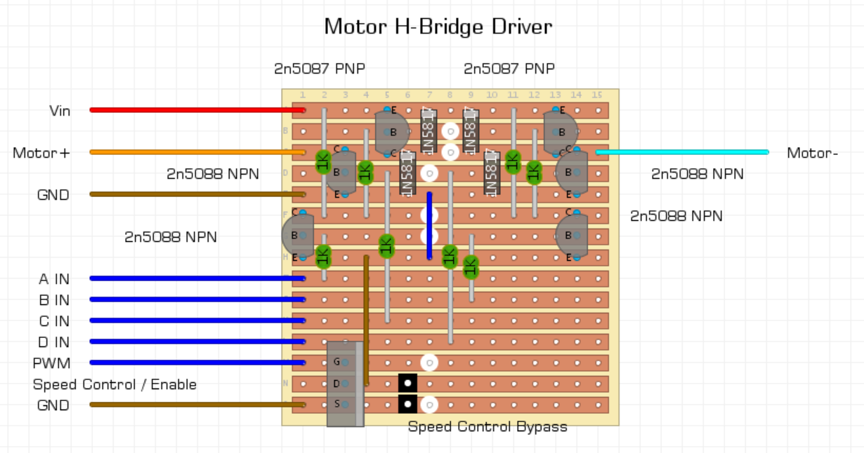
Motor H-Bridge Driver
This is a simple motor driver I wanted to play with after observing a fuel pump layout at work. It used 4 valves and a compressed gas powered pump that could only spin in one direction to both fill and drain the fuel tanks.
Seeing this valve layout in front of me, made the concept I had briefly heard about an “H-Bridge Driver” for motors, suddenly make sense to me. When I got home I build a few different versions of this circuit. Some used MOSFETS, some BJTs, this circuit is the one I had the best results with, however the MOSFET one probably would have worked better if I had more suitable parts available.

The circuit works by opening “valves” on opposing sides, to change the direction current flows through the motor in the middle. To spin the motor forwards, pin A and pin D are pulled high. To run the motor in reverse, pin B and pin C are pulled high.


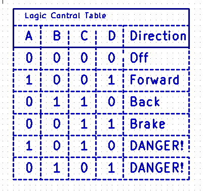
Logic Table for the H-Bridge Driver
This logic table shows the control required for operation. It shows that as well as forward and backwards, there is an additional Brake mode available, as well as two logical inputs that produce dangerous results. This happens if we bring A and C high, and/or B and D high, as in either of these cases there is effectively a short circuit between Vcc and GND.
H-Bridge Driver – Illegal Logic Condition

We need to ensure that we allow some time between alternately driving pins to ensure we do not have a short circuit condition as shown above.
Implementation
This is the layout I made using the schematic above, I also added in a master speed control using a low side MOSFET, although this could probably be done by applying PWM to pins A, B, C & D, this would have significantly increased the complexity of the code required to control the circuit, and I wanted to keep things simple. Ideally this circuit would have some isolation between the Control pins, PWM pin and the microcontroller. Shorting the pads in black takes the speed controller out of circuit to make it function as the schematic above.
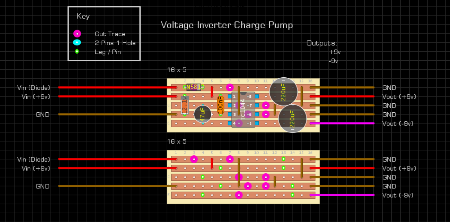
9v Voltage Inverter
This circuit outputs the inverse of the voltage input. Useful for supplying inverted voltage for Positive Ground vintage guitar FX, or for bi-polar power supply requirements for op-amps or synthesiser style circuits.
This layout is adapted from the power supply section of a Mastro: Filter, Sample & Hold.
I included two options for Vin, as some circuits may require as close to Vin as possible for correct function, and the voltage drop over the diode might reduce the voltage too much for some use cases. The 12.1v Zener was documented on the M:F/S&H schematic, and provides some additional overvoltage protection, but removing it will not affect the function of the circuit.

AtTiny85 Neopixel Board with ISP Programming Port
Simple layout for an AtTiny85 circuit that has an ISP header laid out on the board.
This board is configured to run a string of ws2812b or Neopixel addressable LEDs, but this board is easily modifiable for any other projects using AtTiny85s for which you require the ability to reprogram the controller while it is in circuit.
The ISP header works with any of the common tutorials for using Arduino as an ISP programmer for AtTiny85.
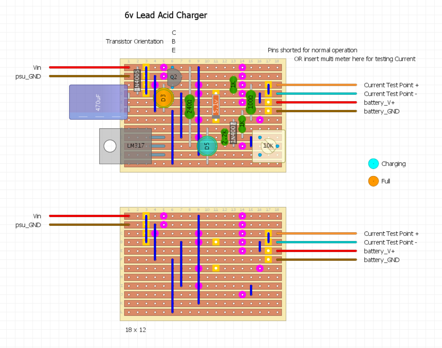
6v Lead Acid Battery Charger
To make sure this circuit is adjusted for the battery it is charging, we need the following information:
| Input: | ||
| Battery Voltage (Vb) | 6 v | |
| Battery Capacity (Cb) | 4.5 Ah | |
| Outputs: | ||
| Charging Voltage (Cv) | No more than 1.5 x Vb | 6 v < Cv <= 9 v |
| Max Charging Current (Cc) | 10% Battery Capacity | 0.45 A / 450 mA |
The trimpot should be adjusted until the output roughly matches the values in the table.
A multimeter can be inserted in series with the battery to keep track of the current, which will drop off as the battery increases in voltage.
If I wanted to make this standalone, I could use the small 7 segment display Volt/Amp meters available from online stores for a few pounds.
This circuit should also be capable of charging 12v Lead Acid Batteries by replacing the 5.1v zener with an 11.1v zener diode.